| [ < ] | [ > ] | [ << ] | [ Up ] | [ >> ] | [Top] | [Contents] | [Index] | [ ? ] |
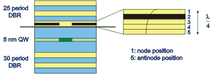
The following code illustrates how to use CAMFR to find laser modes in a cavity, in this case a cylindrical oxidised VCSEL (vertical-cavity surface-emitting laser):
#!/usr/bin/env python

####################################################################
#
# Finds a laser mode in a VCSEL (from COST 268 modelling exercise.)
#
####################################################################

from camfr import *

set_lambda(.980)
set_N(100)
set_circ_order(1)

# Define materials.

GaAs_m   = Material(3.53)
AlGaAs_m = Material(3.08)
AlAs_m   = Material(2.95)
AlOx_m   = Material(1.60)
air_m    = Material(1.00)

gain_m = Material(3.53)
loss_m = Material(3.53 - 0.01j)

set_gain_material(gain_m)

# Define geometry parameters

set_circ_PML(-0.1)

r = 4.0
d_cladding = 4.0

d_GaAs   = .06949
d_AlGaAs = .07963

# Define cross sections

GaAs   = Circ(  GaAs_m(r+d_cladding))
AlGaAs = Circ(AlGaAs_m(r+d_cladding))
air    = Circ(   air_m(r+d_cladding))

ox = Circ(AlAs_m(r) + AlOx_m(d_cladding))
QW = Circ(gain_m(r) + loss_m(d_cladding))

# Set oxide window position.

position = 4 # 1: node, 5: antinode
x = (5. - position) * d_AlGaAs/5.

# Define top half of cavity.

top = Stack( (GaAs(0) + AlGaAs(x)) + ox(.2*d_AlGaAs)           \
    + (AlGaAs(.8*d_AlGaAs - x) + GaAs(d_GaAs)                  \
    + 24*(AlGaAs(d_AlGaAs) + GaAs(d_GaAs)) + air(0)) )

# Define bottom half of cavity.

bottom = Stack(GaAs(.13659) + QW(.00500)                       \
    + (GaAs(.13659) + 30*(AlGaAs(d_AlGaAs) + GaAs(d_GaAs) + GaAs(0))) )

# Define cavity and find laser mode.

cavity = Cavity(bottom, top)

cavity.find_mode(.980, .981)
|
First, we need to divide the cavity in an arbitrary location in a top and a bottom part (the dashed line in fig. 2.2):

We then define two stacks describing these top and bottom part, starting from the dashed line. Defining the cavity is as simple as writing
cavity = Cavity(bottom, top) |
In order to locate a laser mode, we need to vary the wavelength to achieve phase resonance and to vary the material gain in the active region to achieve amplitude resonance. For that, we first had to inform CAMFR which material would provide the gain:
set_gain_material(gain_m) |
From the definition of the waveguide QW, we can see that this device
provides gain in the central part of the active region, while there is a
small constant loss outside of the oxide aperture.
Finally, the command cavity.find_mode(.980, .981) will locate a laser
mode in the wavelength range between 980 and 981 nm. Once it has found
such a mode, it will print out its wavelength and threshold material gain.
There are a few other arguments that can be passed to find_mode() to
control the search process, but for that we refer to the reference guide.
A trick worth pointing out is the use of parentheses to group all the
transverse uniform waveguide sections in the definitions of top and
bottom. These substacks have diagonal reflection and
transmission matrices and can therefore be calculated more efficiently.
By explicitly grouping these diagonal substacks, CAMFR will recognise them
as such, rather than treating the whole stack as completely non-diagonal.
| [ < ] | [ > ] | [ << ] | [ Up ] | [ >> ] |
This document was generated by root on August, 27 2008 using texi2html 1.76.