|
|
|
This page gives a brief overview of some of the main principles behind CAMFR: vectorial eigenmode expansion and perfectly matched layers. For a more in-depth treatment, see our
publications.
|
|
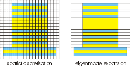
Many traditional modelling tools (FDTD, MoM, FEM, ...) are based on some form of spatial discretisation, meaning that they overlay the structure to be modelled with a grid and then calculate the electromagnetic field at each of these grid points. These approaches work fine and are very general. However, in order to get a decent accuracy, the grid has to be chosen rather fine, which can lead to long calculation times and hefty memory requirements.
|

|
|
CAMFR is based on a different principle called eigenmode expansion. Rather than working with a grid, the structure is divided in a number of layers where the refractive index profile does not change in the z-direction. Many interesting structures are indeed layered in nature, and those that are not can be approximated as such.
| |
Rather than specifying the fields explicitly at a number of grid points, the fields in each layer are written as a sum of the local eigenmodes of that particular layer. This leads to a much more compact representation of the field and therefore shorter computation times. Moreover, contrary to spatial discretisation, the calculation time of a layer is independent of the length of that layer. Also, periodicity or quasi-periodicity is exploited much more easily.
|
|
However, this method requires a discrete set of modes, and in order to achieve this, the structure we want to model is typically enclosed in a metal box. Unfortunately, this can create parasitic reflections: radiation that would otherwise travel freely towards infinity is now completely reflected at the metal boundaries, returns to the structure that we want to study, and disturbs the simulation results.
|
|
In order to alleviate this problem, CAMFR makes use of advanced boundary conditions, the most prominent of which are perfectly matched layers or PMLs. These layers can be thought of as layers with a real refractive index, but with a complex thickness. This complex thickness provides for reflectionless absorption of the incident field, regardless of incidence angle, wavelength or polarisation. The use of these advanced boundary conditions not only improves the accuracy of the model, but also speeds up the computation time, as the metal walls can now be placed much closer to the structure.
|
|
